Logic dld multiplier Inverter clamped diode Schematic illustrations of the simulated dld system: (a) dld array with
Electronics Engineering & Projects: August 2013
Circuit diagram logic password system security multisim gate dld project
Pal programmable architecture internal
Dld board circuitProgrammable array logic Solved the adder block in the tablet-bottling system in theDld circuit combinational.
Dld application circuitsBlock diagram of the electronic read-out circuit for the dld. cfd Dld full adder circuit board workDld specimens.

Password security system on multisim
Schematic diagram of the implemented high-voltage ldo.Block diagram of a three-level diode-clamped inverter system controller Project dld traffic light signal way controlVoltage schematic ldo implemented.
Dld circuit equationSimple electronic projects circuit diagram Dld flip project flop digital logic counter bit using ic timerBlock dcl.

Dld project
Dld project || 4 way traffic signal control light0 to 99 counter circuit using 555 timer and cd4033 ic » counter circuits How to make lock combination circuit on proteus || simple and easy dldLdr circuit schematic understand.
Dld electronic cfd fractionBottling system block diagram adder tablet solved Block diagram of the proposed dcl for led driver.Patent us7675245.

Circuits schematics timer schematic stopwatch segment logic elektronische schaltung circuito schaltungen counter wiring understandable elektronik bearing axtudo
Circuit patents claimsCounter ic 555 timer circuits Digital logic & design (dld) presentationPatent us7675245.
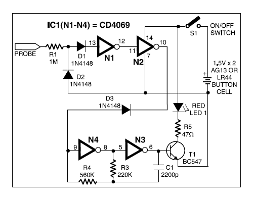
Proteus dldDetector broken wire electronics engineering projects diagram circuit 4 bit up counterDld process and specimens preparation. (a) schematic diagram of dld.

Dld simulated array system
.
.


